ISO 9001 precision machining factory in Dongguan, China — prototypes to production, shipped worldwideinquiry@machined-parts-factory.com+86 176 2154 1688

CNC Milled Industrial Control Enclosures in 6061-T6

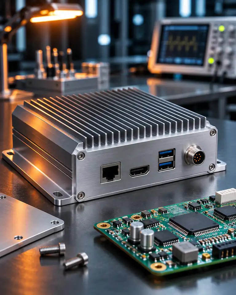
An industrial automation OEM needed a two-part electronics enclosure milled from solid 6061-T6 for a control module. The enclosure had to seal against dust and water, carry heat from power components into external fins, and provide bare metal contact for grounding and EMI shielding.

  • Electronics
Part
Two-piece enclosure (base and lid) with integral fins
Material
6061-T6 aluminum plate
Process
3-axis and 4-axis CNC milling, drilling and tapping
Critical tolerance
Gasket groove ±0.03 mm; lid flatness 0.10 mm
Finish
Bead blast and Type II anodize, contact pads masked
Batch type
Prototype → low-volume production
Inspection
CMM, thread gauges, conductivity check on bare pads

The challenge

A machined control enclosure does three jobs: it protects the electronics, it spreads heat, and it acts as a shield and ground path. Each job places its own demand on the part.

The drawing required:

  • Gasket groove held to ±0.03 mm around the full perimeter of the base, to suit an ingress-protection design target set by the customer
  • Lid flatness of 0.10 mm, so the gasket is compressed evenly at every screw spacing
  • Internal bosses under power components, machined flat so a thermal pad can transfer heat into the wall, with external fins on the opposite side
  • Connector cutouts positioned to match the PCB layout, with tight corner radii
  • Bare aluminum contact pads at the lid joint and PCB ground points for electrical continuity

Machining a deep box from solid plate removes most of the material, so the lid and base face tend to bow. The cosmetic outside surface also had to look uniform, which rules out heavy clamping marks.

Our approach

We built the route around one clean datum and a fixture that supports the thin walls.

  1. DFM review. We matched internal corner radii to standard end mill sizes and suggested reliefs in the connector cutout corners so they could be milled without EDM. We also confirmed which faces needed bare metal.
  2. Roughing both sides. Base and lid blanks were roughed from 6061-T6 plate on both sides, leaving stock for finishing, and then rested to let stress settle.
  3. Datum face. The flange (gasket) face was skimmed and used as the primary datum for all later operations.
  4. Inside features. On a vacuum fixture, the cavity, PCB bosses, thermal bosses and gasket groove were finished. The groove was cut with a single continuous toolpath for a uniform sealing surface.
  5. Outside and fins. The part was mounted on a custom internal support plate that fills the cavity, so the walls could not flex while the external fins were milled.
  6. Side features. Connector cutouts and side holes were machined on a 4-axis rotary setup to keep their positions related to the internal bosses.
  7. Threads. Lid screw holes and PCB mounting holes were tapped; thread inserts were fitted where the drawing called for them.
  8. Finishing. Parts were bead blasted for an even texture, then Type II anodized with the contact pads and grounding points masked.

Quality plan

Inspection covered sealing, thermal contact, grounding and fit with the PCB.

  • First-article inspection of all dimensions on CMM, including gasket groove geometry and lid flatness
  • Thermal and PCB bosses checked for height and flatness relative to the datum face
  • Connector cutout positions reported relative to the PCB mounting holes
  • Threads checked with go/no-go gauges after anodizing
  • Bare contact pads checked with a multimeter for electrical continuity after anodizing
  • Cosmetic inspection for blast uniformity and clamping marks on the outer surfaces
  • Lid-to-base fit checked by assembling a sample set with the specified gasket and screws

Groove dimensions, lid flatness and pad continuity were 100% inspected on production parts. Material certificates were supplied with each order.

What was delivered

We delivered prototype enclosures for the first electronics build and test, then low-volume production lots on the same fixtures and programs. Each delivery included:

  • CMM first-article report for base and lid
  • Per-part records for gasket groove, lid flatness and pad continuity
  • Material certificates for the 6061-T6 plate
  • Masking drawing defining bare contact areas

Ingress-protection, thermal and EMC testing of the assembled module was performed by the customer. DFM notes on corner radii and cutout reliefs were recorded for future enclosure sizes.

Questions about this project

Why machine an electronics enclosure from solid instead of die casting?

Machining from solid needs no die, so it suits prototypes and low to mid volumes and allows design changes between builds. It also gives tighter groove and flatness control. At higher volumes, die casting with machined sealing faces is often more economical.

How is grounding kept on an anodized aluminum enclosure?

Anodic coating is an electrical insulator. Contact pads at the lid joint and PCB ground points are masked before anodizing so they remain bare aluminum, and continuity is checked with a meter after coating.

More projects

All projects

Similar part?

Need a part like this?

Send your drawing and we’ll reply with a process plan and quote.

Chat on WhatsApp