Anodizing Machined Aluminum: Type II vs Type III Guide
Anodizing grows into and out of the aluminum surface, which changes bores, shafts and threads. This guide covers Type II and Type III thickness, masking, color control and how to call out anodizing correctly.
By the Axisform engineering teamPublished Updated 7 min read
Type II anodizing is a sulfuric acid process that produces a thin, dyeable oxide layer, typically 5–25 µm, used for corrosion protection and color on machined aluminum. Type III (hard) anodizing uses colder, more concentrated electrolyte and higher current density to grow a much harder layer, typically 25–75 µm, for wear resistance. Both coatings grow partly into and partly out of the surface — roughly half each way — so critical fits, threads and bores must be designed or masked with that growth in mind.
What is anodizing?
Anodizing is an electrochemical process that converts the surface of aluminum into aluminum oxide. The part is made the anode in an acid bath, and current drives oxygen into the surface. Unlike paint or plating, the coating is not deposited on top of the metal; it is grown from the metal itself, which is why it bonds so well and does not peel.
Freshly anodized oxide is porous. That porosity is what allows dyes to be absorbed, and sealing afterward closes the pores to lock in color and improve corrosion resistance.
The common reference specification is MIL-A-8625, which defines:
Type I — chromic acid anodizing, very thin (roughly 0.5–7.6 µm), used mainly in aerospace for fatigue-sensitive parts.
Type IB and IC — low-temperature or non-chromic alternatives to Type I.
Type II — sulfuric acid anodizing, the standard decorative and protective finish.
Type III — hard anodizing.
It also defines Class 1 (undyed, natural) and Class 2 (dyed). A typical callout reads "Anodize per MIL-A-8625, Type II, Class 2, black."
Type II vs Type III anodizing: what is the difference?
Characteristic
Type II (sulfuric)
Type III (hard)
Typical thickness
5–25 µm (0.0002–0.001 in)
25–75 µm; 50 µm (0.002 in) is a common nominal
Bath temperature
Around room temperature
Near 0 °C
Hardness / wear
Moderate
Very high wear and abrasion resistance
Color options
Wide range of dyed colors
Natural color is gray to bronze; black and some dark colors are practical
Cosmetic quality
Excellent, uniform
More industrial look, color varies with thickness and alloy
Choose hard anodize when the surface slides, rubs or sees abrasive wear: guide rails, pneumatic cylinder bores, gear teeth, clamp jaws, tooling. It is also used when a thicker insulating layer is needed. For a part that only needs to look good and resist corrosion, Type II is cheaper and gives more consistent color.
How much does anodizing change part dimensions?
As a working rule, about half the coating thickness penetrates into the original surface and about half builds up above it. That gives these practical effects:
Outside diameters grow by roughly the full coating thickness (half on each side). A 10.000 mm shaft with a 20 µm coating becomes about 10.020 mm.
Holes and bores shrink by roughly the full coating thickness.
Flat dimensions across two anodized faces grow by roughly the full coating thickness.
60° threads are affected most. Because of the flank geometry, the pitch diameter changes by about four times the build-up per surface. A modest 10 µm build-up can change pitch diameter by around 40 µm, enough to make a tight thread bind.
Practical consequences:
Mask threads or machine them oversize (for internal threads) and undersize (for external threads) so they gauge correctly after coating.
State whether dimensions apply before or after anodize. Without that note, supplier and buyer may inspect against different numbers. Our tolerance guide explains why this matters for tight features.
For Type III, compensate in the machining dimensions. At 50 µm, a bore shrinks by about 0.05 mm, which can consume an entire H7 tolerance.
What is masking and when do you need it?
Masking keeps the anodize off selected areas. Common reasons:
Electrical contact. Anodize is an insulator. Grounding points, contact pads and EMI gasket faces must be bare aluminum.
Precision fits. Bearing bores, dowel holes and press fits that cannot tolerate growth.
Threads that must gauge without rework.
Bonding or welding surfaces after anodizing.
Methods include silicone plugs and caps for holes and threads, vinyl tapes for flat faces and liquid masking lacquers for irregular areas. Each masked area adds manual labor, and masking edges are never perfectly sharp, so tolerance the boundary of a masked zone generously (for example ±0.5 mm) and mark masked areas clearly on the drawing with a hatch or note.
A common alternative to masking for conductivity is to anodize the whole part, then machine or laser-remove the coating on contact areas. Laser removal is clean and repeatable for small pads.
How do you get consistent anodized color?
Color is the most frequent source of disputes on anodized parts. Several variables shift the result even when the process is nominally the same:
Alloy. 6061 and 6063 give the most uniform colors. 7075 can look slightly yellower or darker, and 2024 anodizes less evenly. Cast alloys with high silicon, such as many die-casting alloys, give dull, gray results. See 6061 vs 7075 aluminum.
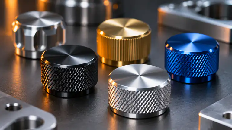
Surface preparation. Bead blasting, brushing or polishing changes how light reflects from the oxide. A bead-blasted black part looks very different from a polished black part.
Coating thickness and dye time. Thicker coatings absorb more dye and look deeper.
Batch and tank. Different lots of dye and different tanks give small shifts.
Material lot. Even within one alloy, different mill lots can respond differently.
To control color:
Supply a physical color sample or agree on an approved "golden sample." Pantone or RAL numbers are a reference, but anodized color is translucent and metallic, so it never matches a printed chip exactly.
Define acceptable range, ideally with light and dark limit samples.
Use the same alloy and the same surface prep for parts that will sit next to each other.
Anodize mating parts in the same batch where possible.
Specify the viewing conditions for inspection (distance, light source).
Black and clear (natural) are the most consistent colors. Bright reds, and especially light colors such as white, are difficult; true white is not achievable with standard dye anodizing.
How does surface finish before anodizing affect the result?
Anodizing does not hide machining marks — it tends to reveal them. Tool marks, scratches and handling marks remain visible under the coating. Common pre-treatments:
Bead blasting gives a uniform matte look and hides fine tool marks. Specify the media grit when the look matters.
Brushing produces a linear grain, popular on consumer electronics and audio faceplates.
Polishing gives a bright, reflective finish, but any defect becomes obvious.
Chemical brightening produces a glossy finish on suitable alloys.
Sharp edges anodize thinly and can chip. Break edges with a small chamfer or radius (around 0.2–0.5 mm) for better coating coverage, especially on Type III.
What design details matter for anodizing?
Rack points. Parts must be held on titanium or aluminum racks with electrical contact. The contact points remain uncoated. Tell the supplier where rack marks are acceptable, typically in a hidden hole or on an internal face.
Blind holes and deep recesses trap solution and gas, causing uneven coating or staining. Through holes are easier.
Assemblies. Anodize parts before assembly; steel inserts, press-fit pins and helicoils must be installed afterward.
Laser marking. Anodized aluminum laser-marks well; marking removes or bleaches the dye for crisp, permanent text.
How should you call out anodizing on a drawing?
A complete callout includes:
Specification and type: "Anodize per MIL-A-8625 Type II Class 2" (or ISO 7599 for decorative anodizing).
Color, with reference sample.
Thickness range, for example 10–15 µm.
Sealing requirement.
Masked areas, identified on the drawing.
Whether dimensions apply before or after anodize.
Pre-treatment: bead blast, brushed or as-machined.
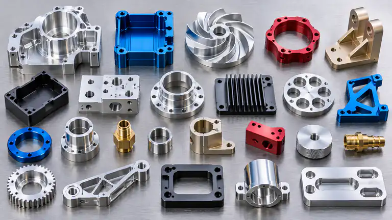
Axisform provides Type II color and Type III hard anodizing together with sandblasting, brushing, polishing and laser marking, so machining allowances, masking and color can be agreed with one team. Send your drawing via our contact page for a review of finish-critical features.
Frequently asked questions
How thick is Type II anodizing?
Type II sulfuric acid anodizing is typically 5–25 µm (0.0002–0.001 in). Decorative parts often use around 10–15 µm, while parts needing more corrosion protection or deeper color use the upper end of the range.
Does anodizing change part dimensions?
Yes. Roughly half of the coating grows outward and half penetrates inward, so outer diameters grow and holes shrink by about the full coating thickness. Threads are affected most and are usually masked or machined with an allowance.
Can you anodize aluminum white?
Not with standard dye anodizing. The oxide layer is translucent, so the metal underneath shows through and white comes out as a pale gray. Clear, black and dark colors are the most consistent options.
Is Type III hard anodizing available in colors?
Hard anodize is naturally gray to dark bronze depending on alloy and thickness. Black is commonly available and some dark colors can be dyed, but bright colors are not practical because the coating is dense and dark.
Written by the Axisform engineering team
Manufacturing and quality engineers at our Dongguan machining factory. Questions about this guide? Email us.
Need parts made to these principles?
Send your drawing and an engineer will reply with DFM notes and a quote within 24 hours.
A good metal knob depends as much on its bore fit and runout as on its finish. This guide covers knurling patterns, materials, finishes and the main ways knobs attach to shafts in audio, appliance and automotive controls.
Sheet metal is usually cheaper for uniform-wall enclosures and brackets, while CNC machining wins on varying thickness and tight tolerances. This guide compares both and explains bend radius and K-factor basics.
Most quality problems with imported machined parts come from requirements that were never written down. This guide walks through the RFQ package, first article approval, inspection documents, Incoterms and shipping.